OEM and Aftermarket Rolling Mill Spare Parts | Drawing-Based Manufacturing

Engineering Solution for High-Precision Eccentric Bushing Machining Modular Fixture System for Stable Industrial Production
Abstract Eccentric bushings are critical components in heavy-duty machinery, steel plant equipment, and precision adjustment systems. Although geometrically simple, eccentric parts require strict control of positional relationships across multiple machining stages. This article presents a structured engineering solution based on a modular fixture system designed for CNC turning of eccentric bushings. The study analyzes reference management, positioning strategy, force transmission, and accuracy control, demonstrating a stable and production-proven approach suitable for industrial environments.
TECH CENTER
Borton Engineering Team
2/15/20262 min read
1. Industrial Background
In eccentric component machining, dimensional precision is primarily determined by fixture stability rather than tool capability.
Typical production challenges include:
Maintaining consistent eccentric distance
Ensuring concentricity between multiple eccentric bores
Preventing cumulative positioning error
Avoiding deformation during clamping
Achieving repeatable accuracy in batch production
Without a unified reference system, multi-stage machining inevitably introduces error accumulation.
For industrial applications such as rolling mill assemblies and heavy mechanical systems, repeatability and reliability are essential.
2. Technical Characteristics of the Eccentric Component
The representative component includes:
Eccentric bore Ø10
Concentric eccentric bore Ø7
90° taper feature
Non-eccentric outer diameter Ø16
The machining sequence requires:
Establishing primary eccentric geometry
Preserving bore-to-bore concentricity
Maintaining eccentric-to-OD positional relationship
This demands precise control of datum transfer between processes.
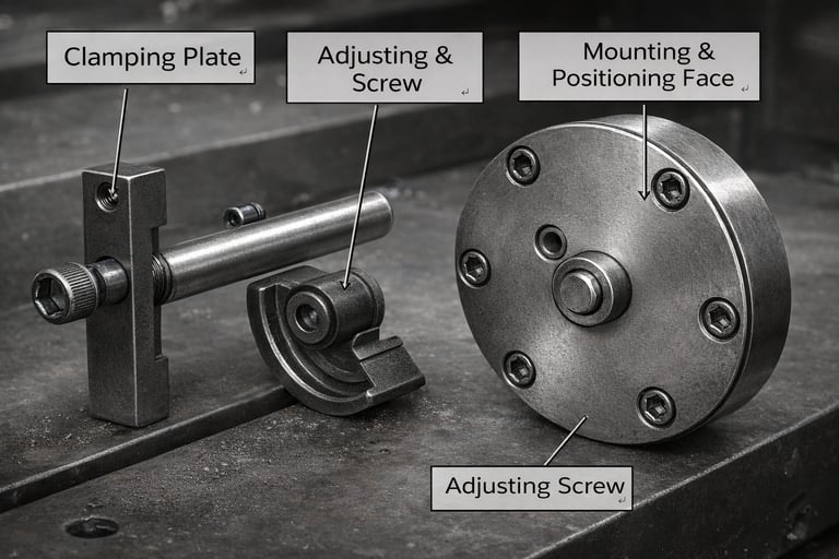
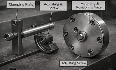
3. Modular Fixture Architecture
3.1 Structural Hierarchy
The fixture system is organized as follows:
Machine Spindle
→ Reference Head (Base Platform)
→ Process-Specific Positioning Cover
→ Workpiece
→ Hydraulic Drawbar Expansion System
The reference head replaces the traditional hydraulic chuck and serves as a permanent datum interface.
Only the positioning cover is replaced between operations.
3.2 Core Engineering Principle
Fixed primary reference + interchangeable functional modules.
By keeping the spindle reference unchanged, the system eliminates repeated datum conversion and significantly reduces cumulative positioning errors.
This design approach prioritizes geometric stability over structural complexity.
4. Process Strategy and Positioning Method
Process 1 – Machining Ø10 Eccentric Bore
Positioning method:
Ø7 cylindrical locator
Tapered drawbar expansion
Uniform radial clamping force
Mechanical principle:
Axial drawbar force
→ Tapered interface
→ Radial expansion of slotted sleeve
→ Symmetrical internal contact
This stage establishes the main eccentric feature under stable clamping conditions.
Process 2 – Machining Ø7 Concentric Bore
Positioning method:
Ø10 bore used as refined datum
Stepped axial positioning
Clamping plate with adjustable pressure control
This ensures concentricity between Ø10 and Ø7 while maintaining eccentric distance.
Controlled clamping force minimizes deformation.
Process 3 – Machining Ø16 Outer Diameter
Positioning method:
Adjustable eccentric correction block
Expansion-based clamping
Fine eccentric adjustment is performed before final OD machining, ensuring full geometric closure.
5. Force Transmission and Structural Stability
Representative force path:
Axial Pull Force
→ Tapered Interface
→ Radial Sleeve Expansion
→ Uniform Contact
→ Stable External Machining
Engineering advantages:
Short force transmission path
Balanced radial load
Reduced stress concentration
Controlled elastic deformation
The large-diameter reference head enhances rigidity and repeatability.
6. Accuracy Control Strategy
Critical precision interfaces:
Head-to-cover fit: approx. 0.01 mm
Drawbar sleeve-to-head fit: approx. 0.03 mm
Accuracy stability depends on:
Precision manufacturing of modular covers
Taper surface quality
Drawbar rigidity
Spindle mounting accuracy
By maintaining a constant base reference, cumulative errors across processes are minimized.
7. Engineering Evaluation
From an industrial engineering perspective, this fixture design represents a mature and reliable solution.
Design Logic
Clear datum management and modular architecture.
Positioning Principle
Expansion clamping combined with precision step location and eccentric correction.
Structural Rigidity
High rigidity reference head and short load path structure.
Industrial Applicability
Well suited for batch production in heavy-duty environments.
This is not an experimental design.
It is a stability-oriented, production-proven engineering solution.
8. Industrial Advantages
High repeatability
Stable eccentric distance control
Reduced deformation risk
Modular maintenance structure
Suitable for heavy mechanical components
For steel plant equipment and rolling mill assemblies, reliability and consistency are more critical than structural novelty.
9. Conclusion
The modular fixture system provides an effective engineering solution for eccentric bushing machining in multi-stage CNC processes.
By fixing the primary reference and switching modular positioning covers, geometric stability is maintained without cumulative error.
At Burton Intelligent Equipment, we focus on practical engineering design that ensures precision under real industrial conditions.
Our approach emphasizes:
Stability
Repeatability
Mechanical integrity
Production efficiency
This philosophy defines our manufacturing and technical development standards.
Contact
Reliable parts, delivered fast worldwide.
Phone
+86-185-7510-7789
Guangdong Burton Intelligent Equipment Co., Ltd © 2026. All rights reserved.